 Home
Home
 Back
Back
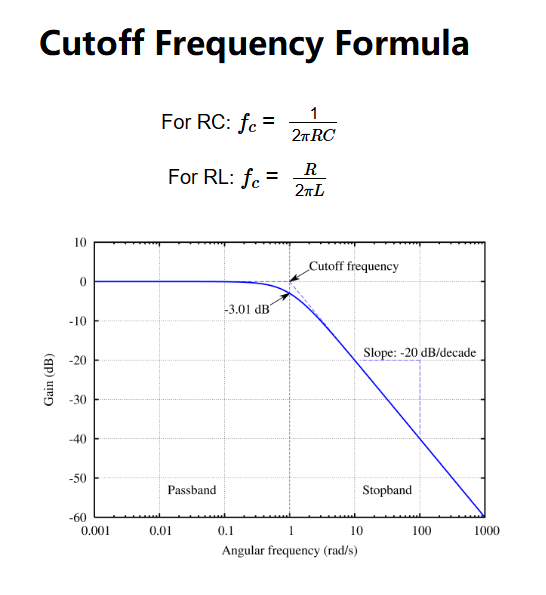
Definition: This calculator computes the cutoff frequency of RC and RL filter circuits, which is the frequency at which the output signal power drops to half its input value (-3 dB point).
Purpose: It is used in electronics to design filters that allow certain frequencies to pass while attenuating others, critical for audio systems, signal processing, and communication devices.
The cutoff frequency is calculated using:
Where:
Steps:
Details: The cutoff frequency defines the boundary between a filter’s passband and stopband, essential for designing low-pass, high-pass, or band-pass filters used in audio equipment, radio receivers, and noise reduction systems.
Tips: Enter the resistance and either capacitance (for RC) or inductance (for RL) with their units. The calculator computes the cutoff frequency in Hz, kHz, and MHz, with 5 decimal places or scientific notation for extreme values (>10000 or <0.0001).
Examples:
Q: What is cutoff frequency?
A: It’s the frequency where a filter begins to significantly attenuate the signal, typically at -3 dB (half power).
Q: How does RC differ from RL?
A: RC filters use a resistor and capacitor (low-pass or high-pass), while RL filters use a resistor and inductor (typically high-pass).