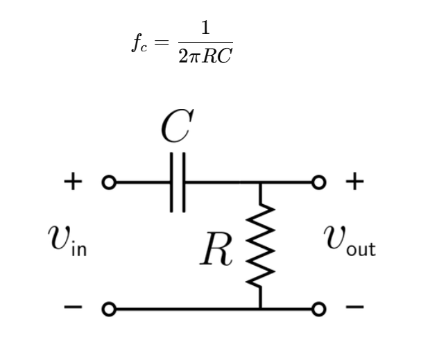
1. What is a High-Pass Filter Calculator?
Definition: This calculator computes the cutoff frequency and gain (for op-amp filters) for high-pass filter circuits, which allow high-frequency signals to pass while attenuating low-frequency signals. It supports RC, RL, and Inverting Op-Amp high-pass filters.
Purpose: It is used in electronics to design filters for applications such as audio systems (e.g., tweeters), noise reduction, and signal processing by removing unwanted low-frequency components.
2. How Does the Calculator Work?
The calculator uses the following formulas based on the filter type:
RC High-Pass Filter: \( f_c = \frac{1}{2\pi R C} \)
RL High-Pass Filter: \( f_c = \frac{R}{2\pi L} \)
Inverting Op-Amp High-Pass Filter: \( f_c = \frac{1}{2\pi R_2 C} \), \( A_v = -\frac{R_f}{R_i} \)
Where:
- \( f_c \) is the cutoff frequency (Hz)
- \( R \) or \( R_2 \) is the resistance (Ω)
- \( C \) is the capacitance (F)
- \( L \) is the inductance (H)
- \( R_f \) is the feedback resistance (Ω)
- \( R_i \) is the input resistance (Ω)
- \( A_v \) is the voltage gain (unitless)
Steps:
- Select the filter type (RC, RL, or Inverting Op-Amp)
- Enter the component values (e.g., resistance, capacitance, inductance, input resistance)
- Convert all units to base SI units (Ω, F, H)
- Calculate the cutoff frequency using the appropriate formula
- For the inverting op-amp filter, calculate the gain using the appropriate formula
- Convert the cutoff frequency to kHz, MHz, and GHz for display
Display format:
- If a value is > 10000 or < 0.0001 (and not zero), use scientific notation (e.g., \( 1.23456e-3 \))
- Otherwise, display with 5 decimal places
3. Importance of High-Pass Filter Calculation
Details: High-pass filters are essential in electronics for removing low-frequency noise, directing high-frequency signals to tweeters in audio systems, and processing signals in communication circuits. Accurate calculation of the cutoff frequency and gain ensures the filter performs as intended.
4. Using the Calculator
Tips: Ensure all inputs are positive. For the inverting op-amp filter, the input resistance must be positive. Use typical values for components to get realistic results.
Examples:
- RC High-Pass Filter: \( R = 1 \, \text{kΩ} \), \( C = 1 \, \text{µF} \):
- \( f_c = \frac{1}{2\pi \times 1000 \times 1 \times 10^{-6}} = 159.15494 \, \text{Hz} \)
- \( f_c = 0.15915 \, \text{kHz} \)
- \( f_c = 0.00016 \, \text{MHz} \)
- \( f_c = 0.00000 \, \text{GHz} \)
- RL High-Pass Filter: \( R = 100 \, \text{Ω} \), \( L = 10 \, \text{mH} \):
- \( f_c = \frac{100}{2\pi \times 0.01} = 1591.54943 \, \text{Hz} \)
- \( f_c = 1.59155 \, \text{kHz} \)
- \( f_c = 0.00159 \, \text{MHz} \)
- \( f_c = 0.00000 \, \text{GHz} \)
- Inverting Op-Amp High-Pass Filter: \( R_2 = 10 \, \text{kΩ} \), \( C = 0.1 \, \text{µF} \), \( R_i = 5 \, \text{kΩ} \):
- \( f_c = \frac{1}{2\pi \times 10000 \times 0.1 \times 10^{-6}} = 159.15494 \, \text{Hz} \)
- \( f_c = 0.15915 \, \text{kHz} \)
- \( f_c = 0.00016 \, \text{MHz} \)
- \( f_c = 0.00000 \, \text{GHz} \)
- \( A_v = -\frac{10000}{5000} = -2.00000 \)
5. Frequently Asked Questions (FAQ)
Q: What is a high-pass filter?
A: A high-pass filter is an electronic circuit that allows high-frequency signals to pass while attenuating low-frequency signals below a specific cutoff frequency.
Q: What is the cutoff frequency?
A: The cutoff frequency (\( f_c \)) is the frequency at which the filter's output power is half of the input power, or the amplitude is reduced to 70.7% (\( 1/\sqrt{2} \)) of the input.
Q: Why use an op-amp in high-pass filters?
A: Op-amps allow for gain control and amplification of the filtered signal, making active filters more versatile for applications requiring signal boosting.
High-Pass Filter Calculator© - All Rights Reserved 2025
 Home
Home
 Back
Back
